

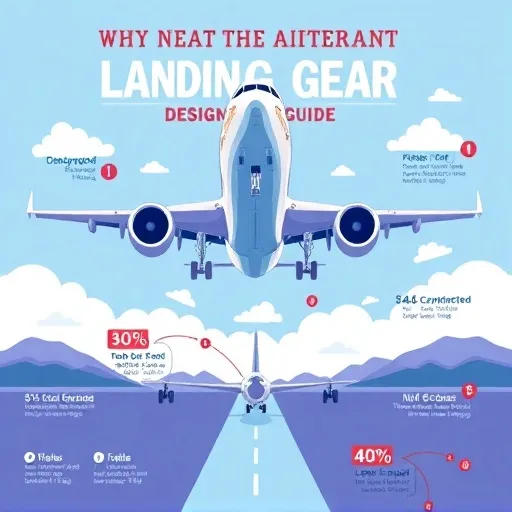
Landing gear dead we
Why Landing Gear Design Matters More Than You Think
Landing gear gets a bad rap. People love to call it "dead weight," and honestly, they've got a point—it usually eats up somewhere between 3% and 6% of an aircraft's maximum takeoff weight, depending on the type. But here's the thing about any solid aircraft landing gear design guide: that so-called dead weight is actually pulling off some of the most punishing work on the entire airframe. Think about what it has to do on every single flight.
- Soak up and dissipate the kinetic energy of touchdown without hammering the airframe
- Hold the aircraft up statically on the ground during loading, unloading, and taxiing
- Deliver stable, controllable directional movement during all ground operations
- Enable serious braking performance, including high-speed rejected takeoffs
- Retract into the airframe with minimal aerodynamic and volumetric penalty
Mess up any one of those, and you're staring down anything from excessive tire wear to catastrophic structural failure. The design brief is genuinely brutal: be as light as possible, as strong as necessary, and as reliable as a component can possibly be. That's the tightrope every aircraft landing gear design guide has to walk.
Landing Gear Configuration Choices: Conventional vs. Tricycle and Multi-Bogie Layouts
The first big decision in any aircraft landing gear design guide is configuration. Broadly speaking, you're picking between conventional (tailwheel) and tricycle layouts, then figuring out how many legs you need and where to put them.
Conventional gear—two main wheels up front and a little tailwheel—still has a loyal following in light general aviation and among taildragger fans. It's lighter and produces lower drag, but ground handling is trickier, with a real risk of ground loops and reduced forward visibility during taxi. Tricycle gear, where a nosewheel steers the aircraft on the ground, dominates modern commercial and military aviation. Why? It's far more forgiving, brakes more effectively, and makes pilot transition training way simpler. For anything above light aircraft weight, tricycle is basically the default.
As aircraft get heavier, the wheel count grows—not because more wheels are inherently better, but because runway pavement can only take so much load per unit area. A heavy widebody might use four-post main gear assemblies with multi-wheel bogies to spread the load. The trade-off? Complexity, weight, and retraction volume. Designers carefully balance pavement loading limits against the structural and packaging penalties of extra legs—a balancing act every good aircraft landing gear design guide has to address head-on.
Shock Absorption Systems: Oleo-Pneumatic Struts and Alternative Energy Absorbers
Here's where things get really interesting. When an aircraft touches down, the vertical velocity at contact might be around 2 to 3 meters per second for a normal landing—and considerably higher in a hard landing. The shock absorber—usually an oleo-pneumatic strut—has to swallow that energy and convert it into heat without transmitting a damaging spike load into the wing or fuselage structure.
An oleo strut combines a gas spring (typically nitrogen) with a hydraulic damper (oil forced through an orifice). On compression, the gas compresses and stores energy, while oil gets forced through a metering orifice, dissipating energy as heat. The clever part is the metering: designers tune the orifice geometry so the damping force is high during compression and lower during rebound, giving a smooth energy-absorbing cycle instead of a bouncy pogo-stick effect.
Modern designs increasingly use adaptive damping or semi-active systems, where valve settings adjust based on sensor data. This lets a single gear design handle both the gentle touchdown of a light landing and the extreme loads of a hard, high-sink-rate arrival without being over-stiff in normal operation. Any current aircraft landing gear design guide worth its salt covers this shift toward smarter damping.
Not every aircraft uses oleo struts, though. Light aircraft frequently rely on spring steel or rubber-in-compression designs—simpler and cheaper, but less efficient at energy absorption. Some specialized designs use leaf springs or composite flexures. For very light unmanned systems, even elastomeric dampers can do the job. The choice depends heavily on sink rate requirements, weight, and cost targets.
Structural Design and Material Selection: Load Cases and Fatigue Considerations
Landing gear structures must withstand some of the highest concentrated loads in the entire aircraft. The main fittings transfer loads into the wing spar or fuselage frame, and fatigue is a constant concern because gear experience repeated high-stress cycles—every landing, every taxi bump, every brake application.
High-strength steel alloys remain the workhorse for struts and axles thanks to their excellent strength-to-fatigue performance and forgiving damage tolerance. Aluminum alloys show up in some secondary structures and linkages, while titanium is used selectively where weight savings justify the cost. Composites have made inroads in fairings, doors, and some secondary structural elements, but primary load paths in landing gear are still overwhelmingly metallic—for good reason. Certification authorities demand proven fatigue behavior, and metals offer well-understood, predictable performance.
Surface treatments matter enormously. Shot peening, plating, and protective coatings combat corrosion and improve fatigue life. In coastal or humid operating environments, corrosion prevention can be the difference between a 20-year gear life and a 10-year one. It's a detail that every thorough aircraft landing gear design guide flags as non-negotiable.
A proper design process considers a long list of load cases, including vertical touchdown at maximum sink rate and maximum weight, combined vertical and horizontal loads during landing with drift or sideload, spring-back and rebound loads, taxi and ground handling loads (including turning and towing), braking loads (especially rejected takeoff scenarios), ground resonance and shimmy dynamics, and crashworthiness requirements where the gear is designed to fail in a controlled, energy-absorbing way. Each one must be analyzed with appropriate safety factors, typically defined by certification specifications that vary somewhat between jurisdictions but converge on similar principles.
Wheels, Tires, and Brakes: Carbon-Carbon Brakes and Anti-Skid Systems
The wheel and brake assembly is where a huge amount of engineering gets packed into a small space. Modern carbon-carbon brakes are remarkable: lighter than steel brakes, they handle enormous thermal loads and maintain performance at temperatures that would destroy conventional friction materials. A rejected takeoff can push brake temperatures past 1,000°C, and the design must ensure the assembly survives—and preferably remains serviceable—after such an event.
Tire design is equally critical. Tire pressure, footprint, and tread configuration all affect pavement loading, wear rates, and the aircraft's ability to operate from different runway surfaces. Designers work closely with tire manufacturers to match specifications to the aircraft's weight and operational profile. Anti-skid systems, meanwhile, modulate brake pressure to prevent wheel lock-up and maintain directional control—a system that must be robust enough to handle everything from dry runway to standing water to contamination. Every credible aircraft landing gear design guide treats this trio as a single integrated system, not three separate parts.
Retraction, Steering, and Systems Integration: Hydraulic vs. Electric Actuation
Most retractable gear uses hydraulic actuation, though electric actuation is gaining ground as more-electric aircraft architectures mature. Retraction kinematics are a puzzle in themselves: the gear must fold into a bay with minimal volume while avoiding interference with structures, systems, and doors. Sequencing, uplocks, downlocks, and emergency extension systems all add complexity—and every one of them is a potential single point of failure that must be mitigated.
Nosewheel steering ranges from simple free-castering designs to fully powered, tiller-controlled systems with significant authority. The design choice affects taxi handling, crosswind capability, and pilot workload. Ground handling—towing, jacking, and maintenance access—also shapes the design in ways that aren't always obvious from the outside. A complete aircraft landing gear design guide can't skip these integration headaches, because they're where projects quietly fall apart.
Testing and Certification: Drop Tests, Fatigue Testing, and Flight Validation
No aircraft landing gear design guide would be complete without discussing validation. Drop tests remain a cornerstone: a full-scale gear assembly is dropped from a controlled height onto a force plate to measure loads and energy absorption against predictions. Fatigue testing subjects the gear to hundreds of thousands of simulated cycles. Iron bird rigs test retraction and hydraulic systems on the ground before flight. And then there's flight testing, where real landings at progressively more demanding conditions confirm the analysis.
Certification requirements are stringent and non-negotiable. Designers must demonstrate compliance with structural, fatigue, and systems safety requirements, often through a combination of analysis, test, and inspection. The documentation burden alone is substantial—but it's what keeps the accident rate as low as it is.
Emerging Trends in Landing Gear Design: Electrification, Additive Manufacturing, and Predictive Maintenance
Landing gear design isn't standing still, and any forward-looking aircraft landing gear design guide needs to track where things are heading. Several trends are shaping the next generation of systems:
- Electrification: Electric actuation for retraction and braking is reducing hydraulic complexity and enabling more integrated health monitoring.
- Predictive maintenance: Sensors embedded in struts and brake assemblies now feed data-driven maintenance models, catching wear before it becomes a failure.
- Additive manufacturing: Complex brackets and fittings are increasingly produced through metal additive processes, reducing part count and weight.
- Advanced materials: New high-strength alloys and selective composite use continue to chip away at weight.
- Autonomous ground operations: As taxi automation matures, steering and braking systems must integrate with autonomy architectures.
Industry professionals consistently emphasize that these innovations must clear the same high bar for safety and reliability as established designs. Novelty is never a substitute for demonstrated performance.
Practical Takeaways for Designers and Enthusiasts: Load Cases, Fatigue, and Maintenance Access
If you're approaching landing gear design—whether as a student project, a career transition, or a design review—here are the principles worth keeping front of mind, the stuff a good aircraft landing gear design guide keeps hammering on:
- Start with the load cases, not the hardware. Understand the energy and load envelope before sketching struts.
- Respect fatigue. Every cycle counts, and stress concentrations are where failures begin.
- Design for maintenance. Gear that's hard to inspect or service will be poorly maintained.
- Validate relentlessly. Analysis predicts; testing confirms. Do both.
- Keep weight honest. Every kilogram in the gear is a kilogram not spent on payload or fuel, but under-designing is far worse than over-designing.